There is a specific kind of satisfaction that comes with stepping onto a warm floor during the winter months. It is an invisible luxury and can truly transform the living experience. However, that invisible comfort relies on a well-planned underfloor heating layout.
Whether you are embarking on a self-build project, extending your kitchen, or renovating a drafty Victorian terrace, the success of your system is determined by the precision of the design.
A poorly planned underfloor heating layout can lead to cold spots, inefficient energy bills, and even structural issues with your flooring.
In this guide, we will walk you through everything you need to know about planning a professional-grade underfloor heating layout, from initial heat loss calculations to the final CAD design.
Preparation and heat loss
Before you start your underfloor heating journey, you need to understand the environment the system will live in. You cannot guess how much heat a room needs.
Heat loss considerations
Underfloor heating (UFH) is a low-temperature system. Unlike traditional radiators that get very hot quickly, UFH operates at lower temperatures over a larger surface area. Therefore, your underfloor heating layout must be designed to overcome the heat loss of the building.
If your home has modern insulation and double glazing, your heat loss will be low, allowing for wider pipe spacing. If you are renovating an older property with solid stone walls, your underfloor heating layout will need to be much denser to compensate for the heat escaping through the structure.
Room usage and fixed furniture
It is essential during these early planning stages to identify dead zones where heat is not required or could even be damaging.
- Do not run pipes under kitchen islands or units. It wastes energy and can cause food in base units to spoil.
- Avoid placing pipes directly under shower trays or bath voids.
- Large, heavy fixed wardrobes should be accounted for in the underfloor heating layout to avoid trapped heat.
Insulation and floor build-up
The heat should go up, not down. Without high-quality floor insulation (such as PIR boards), you could lose up to 50% of your heat into the ground. Your underfloor heating layout must take into account the total height of the insulation, the pipework, the screed, and the final floor finish.
The anatomy of a system
A water-based (hydronic) underfloor heating layout consists of several key components that must work in harmony.
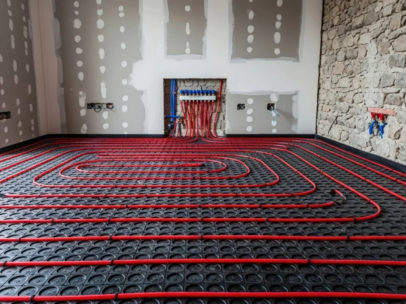
The manifold
The manifold is the distribution point for the warm water. It is where all your pipe loops start and end. Ideally, the manifold should be placed centrally in the property. This reduces the length of dead leads (pipes travelling through hallways to reach their destination), ensuring your underfloor heating layout is as efficient as possible.
It also needs to be accessible for future maintenance, usually inside a utility cupboard or under the stairs.
Zoning
One of the greatest benefits of UFH is zoning. This allows you to heat the kitchen to 21°C while keeping the bedrooms at a cooler 18°C. When planning your underfloor heating layout, every room should ideally be its own zone, though very large rooms may require multiple pipe loops to cover the area effectively.
Pipe spacing and patterns
Pipe spacing is the core of your underfloor heating layout design.
Below are some popular layouts to consider:
- 100mm spacing: Typically used in high heat-loss areas like conservatories or bathrooms.
- 150-200mm spacing: The standard for well-insulated modern living areas.
Water-based system types
When designing your underfloor heating layout, the type of system you choose will dictate the installation method.
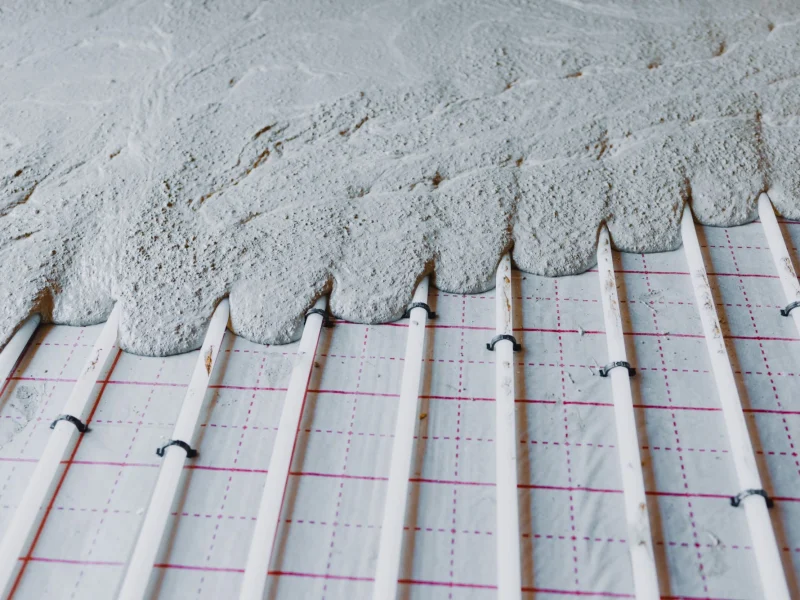
- Screed systems: The most common for new builds. Pipes are clipped to insulation and buried in 50–75mm of sand and cement or flow screed.
- Low-profile systems: Perfect for renovations. These use pre-routed boards that sit on top of the existing floor, adding as little as 15mm to the floor height. Your underfloor heating layout follows the pre-cut channels in the boards.
- Joisted systems: For first floors or timber-frame homes. Pipes can be installed between or over joists using heat-spreader plates, or fitted between joists within a dry mix screed system. Routed OSB boards can also be used, acting as both the pipe carrier and structural deck.
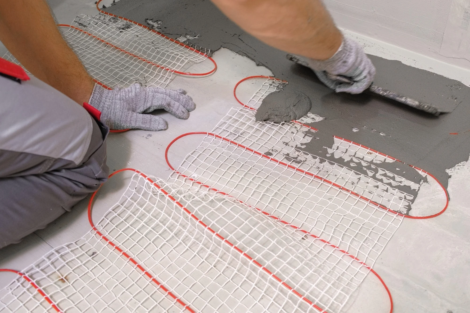
While electric UFH systems are great for small, single-room retrofits like a small ensuite, water UFH systems are the go-to for whole-house efficiency and long-term running costs.
How to plan your layout
Designing an underfloor heating layout is a methodical process. Each decision builds on the last, and small details can have a noticeable impact on how the system performs once installed.
Breaking the process into stages makes it easier to visualise how your layout comes together and ensures nothing important is overlooked.
Step 1: Accurate measurements
Precision is critical. Rooms should be measured as accurately as possible, including the position of doorways, windows, and any large, glazed areas. These features influence heat loss and pipe routing.
It is equally important to think ahead about where the manifold will be located, as this will determine how each loop begins and ends.
Step 2: Define your zones
As mentioned earlier in the blog post, zoning allows different areas of the home to be controlled independently, improving both comfort and efficiency.
As a general rule, separate rooms should be treated as individual zones. This gives you greater control over temperatures and ensures that each space is heated according to how it is used.
Step 3: Choose your pipe pattern
The pipe pattern plays a key role in how evenly heat is distributed across the floor.
Two common approaches are typically used in a professional underfloor heating layout. A serpentine pattern runs the pipe back and forth, making it suitable for smaller or more complex spaces.
A counter-flow (spiral) pattern works by balancing the warm flow against the cooler return, helping to maintain a consistent surface temperature throughout the room.
Step 4: Plan flow and return routes
Every pipe loop must begin and end at the manifold. This flow and return arrangement needs to be planned carefully to avoid congestion in certain areas.
If multiple pipes are routed too closely together, particularly in transitional spaces like hallways, it can lead to unintended hot spots. A well-considered layout keeps pipe distribution balanced, ensuring heat is delivered where it is needed without overloading specific zones.
Common mistakes to avoid
Planning an underfloor heating layout requires precision planning. Here are the most frequent errors we see from DIYers and non-specialist contractors:
- Water cools as it travels. If a single pipe loop is too long (usually over 100m-120m), the end of the run will be cold. Professional CAD designs ensure loops are perfectly balanced.
- A thick wool carpet with a heavy tog underlay acts as an insulator. If your underfloor heating layout doesn’t account for this, the heat will never reach the room.
- Attempting tight turns without following a designated underfloor heating layout pattern can kink the PEX pipe, restricting flow and potentially causing leaks.
- Pipes should never cross over each other in the screed. This creates hot spots and can lead to the screed cracking.
These are not uncommon issues, and most of them come down to one thing: the absence of a properly engineered layout.
The benefits of professional CAD design
An underfloor heating layout design should always be handled by an expert using CAD (Computer-Aided Design) software. Here’s why it matters:
- It improves precision by calculating the exact length of each pipe run and loop layout, helping to avoid material shortages, waste, or unnecessary on-site adjustments.
- It ensures balanced system performance by setting correct flow rates for each circuit so the manifold is properly balanced and heat is distributed evenly throughout the property.
- It provides accurate room-by-room heat loss calculations so each space is designed to meet its specific heating demand efficiently.
- It improves overall efficiency and reliability by reducing installation risk and ensuring the system is properly designed for long-term performance.
Why choose Warm-Flo?
A well-performing underfloor heating system is the result of careful planning, accurate calculations, and a layout that has been designed with purpose. At Warm-Flo, our focus is on delivering that level of precision without overcomplicating the process.
Rather than leaving gaps or assumptions, each stage of the installation is defined so you always know what comes next and what is required from you.
1. Consultation
Every project starts with understanding your space. You provide floor plans along with details about insulation and floor finishes. These inputs form the foundation of the design and ensure that the system is tailored to real conditions, not estimates.
2. CAD design
Using this information, a bespoke layout is created through our CAD design service. This includes pipe spacing, circuit design, manifold placement, and flow considerations. The goal is to produce a layout that distributes heat evenly while maintaining system efficiency.
3. Specification
Once the design is complete, it is translated into a full specification. This outlines exactly what components are needed, removing uncertainty and helping to avoid unnecessary costs or missing items during installation.
4. Supply
All required components can then be sourced directly. From core system parts like manifolds and pumps to pipework and controls, everything is aligned with the original design to ensure compatibility and performance.
5. Ongoing support
Installation is often where questions arise. Support remains available throughout this stage, helping you stay aligned with the design and ensuring the system is installed as intended.
Ready to start your project? Get in touch with our team today for a tailored water or electric underfloor heating design and CAD layout support.