With the UK underfloor heating market now valued at £226 million and hydronic (wet) systems commanding a 59% dominant share of the sector, UFH has moved from a luxury add-on to an industry standard.
But a wet underfloor heating system that performs well needs a strong specification long before ordering a single component.
Get the spec right and the installation follows a logical sequence. If you rush into it then you’re building in problems that are expensive and disruptive to fix once the screed is down.
This guide walks you through the wet UFH specification process, from first site assessment to system sign-off. It’s written for heating and plumbing tradespeople who know their way around a heating system and want a practical framework for approaching UFH projects with confidence.
Start with the right information
Before any design work begins, you need a clear picture of what you’re working with. These aren’t details you gather later – they shape every decision in the wet UFH specification.
The most important questions to answer upfront:
New build or retrofit?
In a new build, you have control over the floor build-up and can design into a known thermal environment. In a retrofit, the floor is already there, which often means overlay systems, tighter tolerances and lower flow temperatures to protect the existing structure.
What’s the heat source?
A system running off a gas boiler can operate at 50–55°C and is relatively forgiving. A system paired with an air source heat pump needs to run at 35–45°C to operate efficiently. That changes your pipe spacing, floor build-up, and the precision required across the whole wet underfloor heating system spec.
How will each room be used?
Bathrooms and kitchens have different response time expectations to bedrooms or living areas. Open-plan spaces with high glazing lose heat very differently to well-insulated inner rooms.
If any of these questions are unanswered at the start, the rest of the specification is built on assumptions and that’s where problems begin.
Don’t skip heat loss calculations
If there’s one thing that separates a properly designed wet underfloor heating system from one that was put together on a whim, it’s whether a heat loss calculation was carried out.
A heat loss calculation considers floor area, ceiling height, wall construction, glazing type and area, insulation levels, and the design outdoor temperature for your location. The output tells you the heat demand for each individual room.
That figure is what drives everything else in the specification, including:
- Pipe centres and spacing
- Flow rates and circuit lengths
- Manifold sizing
- Zone configuration
Without it, you might end up with circuits that are unbalanced, rooms that run cold while others overheat, or a manifold that can’t deliver the flow rates the system needs.
It’s also the document you stand behind. If a customer asks why a room has a specific pipe layout or why the system runs at a particular flow temperature, a heat loss calculation is the answer.
Warm-Flo’s design team carries out full heat loss calculations as part of our full underfloor heating system design service, including layouts, material schedules and full system specifications.
If you’d rather hand this stage to someone with the technical resource to do it properly, that’s what the service is there for.
Designing the pipe layout and circuit configuration
Once you have your heat loss data, you can design the pipe layout. The three key variables are pipe spacing, circuit length, and manifold configuration.
Pipe spacing
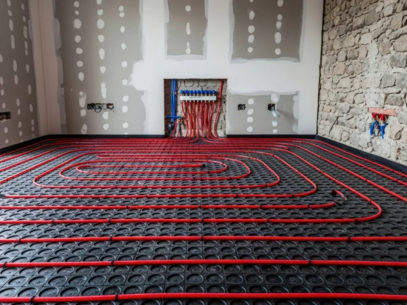
Pipe spacing is typically 100mm, 150mm, or 200mm between centres, depending on the heat output required.
100mm spacing is used in high heat-loss areas such as conservatories, bathrooms, and rooms with significant glazing, while 150mm spacing is standard for well-insulated modern living areas.
200mm spacing works in rooms with low heat demand or where surface temperature needs to be kept moderate, for example, under certain timber floors.
Circuit length
Each circuit running from the manifold should be as close in length to the others as possible. This keeps flow resistance roughly equal, which means the system can be balanced without excessive compensating adjustment.
As a general guide, 100m is a reasonable upper limit for 16mm pipe at standard flow rates. In practice, design circuits by room or zone rather than attempting to run one long circuit across multiple areas.
Manifold sizing
Each manifold port serves one circuit, so a six-room layout requires at least a six-port manifold. Specify manifolds with flow and return gauges, automatic air vents and isolation valves on each circuit. These are what make the system commissionable and serviceable.
Zone control configuration should be agreed at this stage too. Following recent updates to building regulations, specifically Part L, when a new heating system is installed or an existing heat source is fully replaced, every room or zone must have independent thermostatic controls. For wet underfloor heating systems, this means using dedicated room thermostats paired with thermal actuators on the manifold to control the flow to individual loops. Your controls specification (thermostats, actuators, zone valves, or a smart control system) should be part of the specification from the outset.
Floor build-up and covering compatibility
The floor construction determines how your wet underfloor heating system will behave once it’s running.
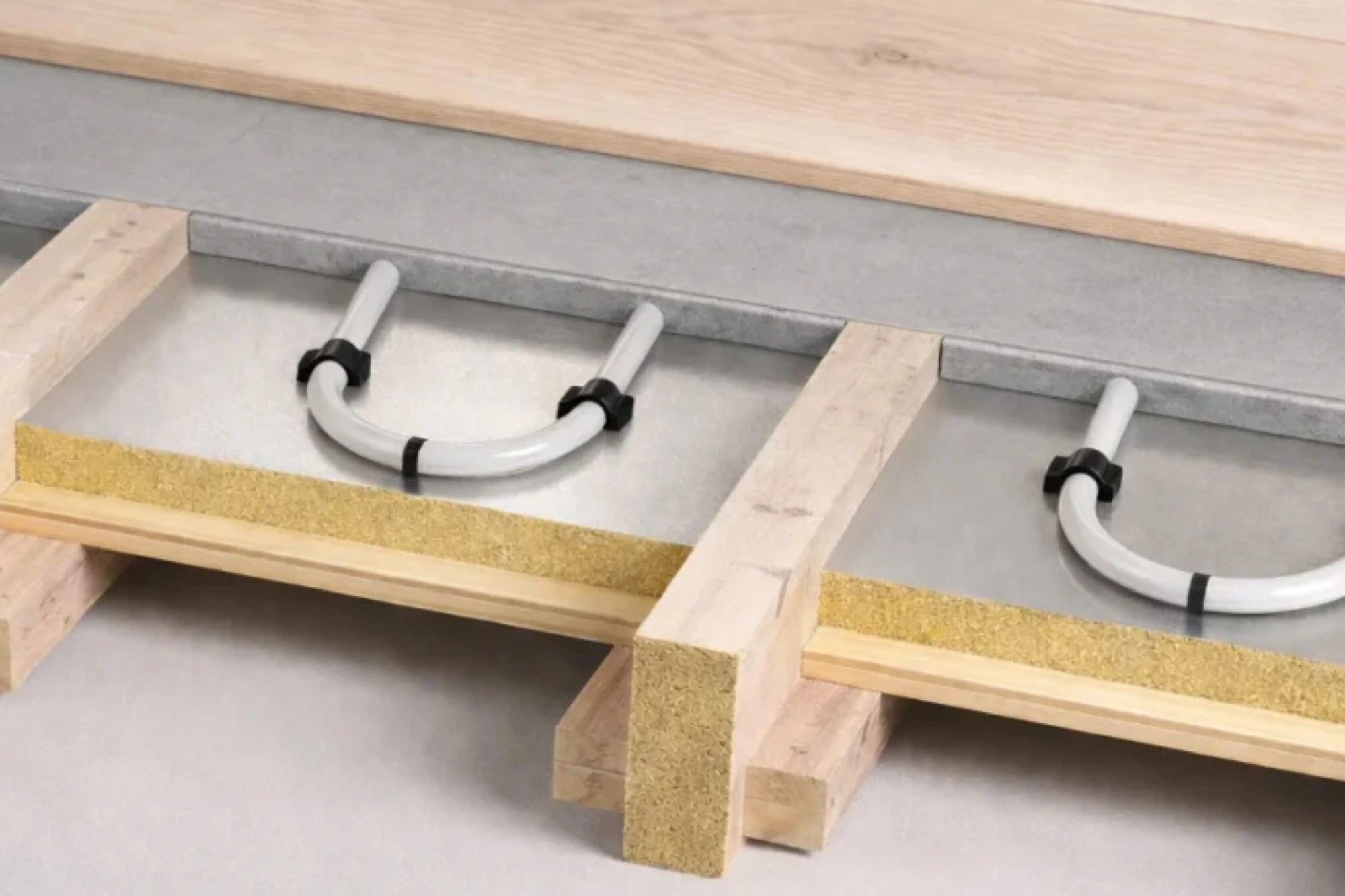
A deep, well-insulated screed over a concrete subfloor stores heat, takes longer to respond, and holds temperature well. A low-profile overlay system over timber responds faster but has less thermal mass to draw on. Neither is wrong, but the specification needs to reflect which one you’re working with.
A few things to confirm before the design is finalised:
Insulation specification
For traditional wet systems laid in screed, insulation should meet Building Regulations requirements – typically 25mm PIR board as a minimum, though more may be required depending on what’s beneath. Insulation is what stops the system heating in the wrong direction.
Dead zones
Don’t run pipe under kitchen units, islands, or fixed cabinetry. It wastes energy and can trap heat, potentially making warranties on the furniture itself void.
Floor coverings
Most hard surfaces such as tile, stone, and polished concrete are well-suited to UFH. Engineered timber can work within the correct moisture content and temperature limits. Thick carpet and solid timber are more problematic. As a rule, the total thermal resistance of the floor finish and any underlay shouldn’t exceed 0.15 m²K/W if you want the system to perform as designed.
If the client hasn’t chosen their floor covering yet, it is worth advising them now. It affects the flow temperature, the pipe spacing, and potentially the warranty position on the floor finish itself.
Controls, commissioning and handover
Controls are often the last thing on the list, and one of the first things that generates callbacks. A well-designed wet underfloor heating system with poorly configured controls will frustrate the end user and can reflect badly on the installer.
Specifying UFH controls
Smart thermostats with programmable schedules are the standard expectation. For systems connected to heat pumps, controls need to be compatible with weather compensation. It is worth specifying controls from a manufacturer when technical support is accessible.
Commissioning
Follow a proper sequence:
- Pressure test all circuits before screeding.
- Allow the screed to cure for the manufacturer’s recommended period before introducing heat.
- Raise flow temperature gradually over several days to allow the screed to settle and any residual moisture to escape. Forced drying of a newly laid screed is one of the most common causes of cracking and early system problems.
Handover
The customer should leave with a clear understanding of how the system works, what to expect during the initial warm-up period, and how to adjust their controls. A simple written handover note takes ten minutes to put together and prevents a significant proportion of post-installation enquiries.
The importance of a wet UFH system specification
Planning your underfloor heating layout is essential. A specification is what protects the installation, the customer relationship, and your reputation.
A system that underperforms because it was never properly specified is difficult to fix without lifting floors. In contrast, a system that was designed correctly from the outset, with proper heat loss calculations and a well-considered layout, is one that works optimally year after year.
At Warm-Flo, we eliminate the guesswork by handling the entire process for you, delivering bespoke CAD designs, precise component specifications, and direct stock supply, all backed by ongoing technical support. We streamline every stage so you can approach your next water or electric UFH installation with absolute confidence.
If you’re approaching a UFH project and want support with system design, talk to the team at Warm-Flo.